How do Ductile iron Grooved fittings sizes differ for sanitary applications compared to standard plumbing systems?

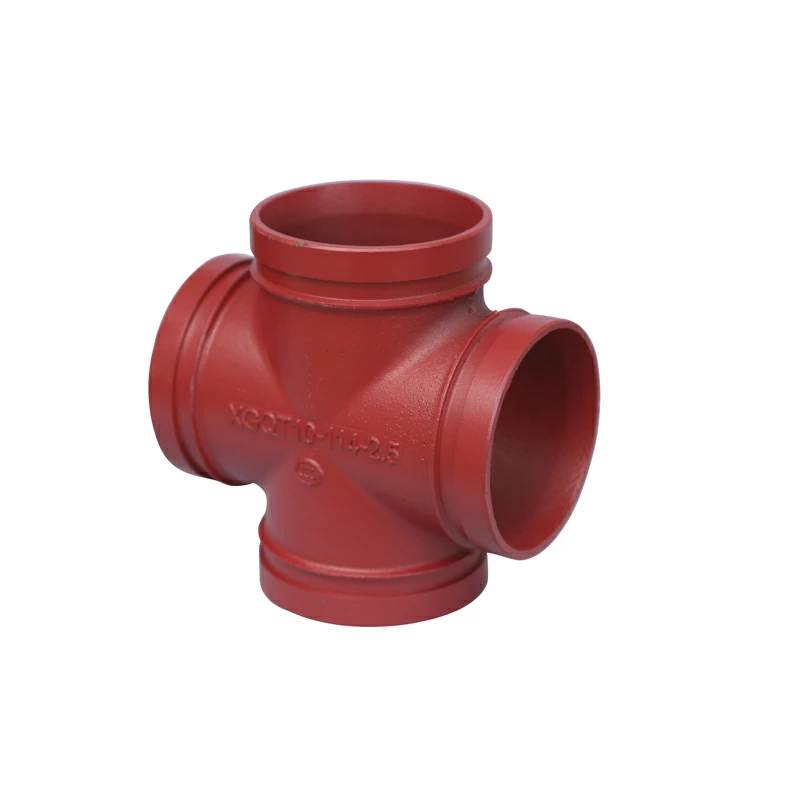
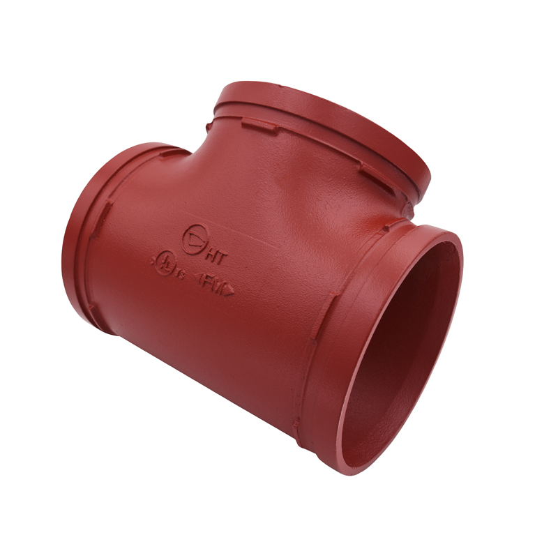
Ductile iron grooved fittings sizes for sanitary applications may differ from those used in standard plumbing systems in several ways:

  1. Size Range: In sanitary applications, ductile iron grooved fittings may be available in a narrower range of sizes compared to standard plumbing systems. Sanitary systems typically use smaller diameter pipes and fittings, so the range of sizes for grooved fittings in these applications may be limited to smaller dimensions.
  2. Material Composition: While both standard and sanitary grooved fittings are typically made of ductile iron, fittings used in sanitary applications may have additional requirements for material composition to meet sanitary standards. This may include specifications for the purity of the iron and the absence of certain contaminants that could affect water quality.
  3. Surface Finish: Grooved fittings used in sanitary applications often require a smoother surface finish compared to those used in standard plumbing systems. This helps to minimize the risk of bacterial growth and contamination in sanitary piping systems, where maintaining hygiene is a priority.
  4. Hygienic Design: Fittings for sanitary applications may incorporate design features that promote hygiene and ease of cleaning. This could include smoother transitions between pipe sections, fewer crevices or dead spaces where contaminants could accumulate, and easier disassembly for cleaning and maintenance.
  5. Certifications and Compliance: Fittings used in sanitary applications may need to meet specific certifications and regulatory requirements related to sanitation and food safety. Ductile iron Grooved fittings This could involve compliance with standards set by organizations such as NSF International or the 3-A Sanitary Standards.
  6. Connection Types: While grooved connections are commonly used in both standard plumbing and sanitary systems, the specific type of grooved coupling or fitting may vary depending on the application. Sanitary systems may require fittings with specialized gaskets or seals to ensure a hygienic seal and prevent contamination.
  7. Application Specificity: Grooved fittings used in sanitary applications may be designed for specific uses within the system, such as connections to equipment or fixtures in food processing facilities, pharmaceutical plants, or other industries where sanitation is critical.

Overall, while the basic concept of ductile iron grooved fittings remains the same across both standard plumbing and sanitary applications, there are differences in size, material composition, surface finish, design features, certifications, and application specificity that reflect the unique requirements of sanitary piping systems. These differences ensure that grooved fittings used in sanitary applications meet the highest standards for hygiene, sanitation, and regulatory compliance.

What are the tolerances for grooved tee dimensions according to industry standards?

The tolerances for grooved tee dimensions can vary depending on the specific industry standards and the manufacturer’s specifications. However, in general, industry standards such as those set by organizations like the American National Standards Institute (ANSI) or the International Organization for Standardization (ISO) provide guidelines for tolerances on grooved tee dimensions.

Here are some typical tolerances for grooved tee dimensions according to industry standards:

  1. Outside Diameter (OD):
    • Tolerances for the outside diameter of grooved tees may range from ±0.02 inches (±0.5 mm) to ±0.05 inches (±1.27 mm), depending on the size and material of the tee.
    • These tolerances ensure that the grooved tee’s outer dimensions remain within specified limits to facilitate proper assembly with grooved-end pipes and fittings.
  2. Wall Thickness:
    • Tolerances for the wall thickness of grooved tees may range from ±10% to ±20% of the specified wall thickness, depending on the manufacturing process and material.
    • These tolerances ensure that the wall thickness of the grooved tee meets the required strength and pressure rating for the intended application.
  3. Center-to-End Dimensions:
    • Tolerances for the center-to-end dimensions of grooved tees may range from ±1/16 inch (±1.59 mm) to ±1/8 inch (±3.18 mm), grooved tee depending on the size and configuration of the tee.
    • These tolerances ensure that the grooved tee’s overall dimensions meet the specified length requirements and allow for proper alignment and installation in the piping system.
  4. Angular Alignment:
    • Tolerances for angular alignment, particularly for angled tees such as 45-degree or 90-degree tees, may range from ±1 degree to ±3 degrees, depending on the size and application.
    • These tolerances ensure that the grooved tee maintains the specified angle relative to the piping system, facilitating proper flow and alignment.

It’s important to note that these tolerances may vary between manufacturers and specific product lines. Additionally, certain applications or industries may have more stringent tolerance requirements to meet regulatory standards or project specifications. Therefore, consulting the manufacturer’s documentation or industry standards relevant to the specific application is recommended to ensure compliance with tolerances for grooved tee dimensions.

PI-6000A Powerful & Intuitive Circuit Breaker Tester

The PI-6000 is a versatile primary injection tester capable of testing circuit breakers up to 6,000 amperes frame size. Its primary applications are for testing low-voltage molded-case and metal-clad AC circuit breakers. The unit may also be used for high-current applications such as ratio transformers and heat runs. The PI-6000 runs on 208-240VAC and 480VAC. The tester has been designed and built with a focus on reliability, durability, and ease-of-use.

Overview

The PI-6000 is a rugged & durable primary injection test set capable of testing circuit breakers up to 6,000 amperes frame size. It incorporates an output transformer with dual primaries to facilitate its use on power sources of 480 VAC as well as 208-240 VAC. The unit also includes dual secondaries to provide optimal impedance matching to a wide range of circuit breaker sizes. An internal voltage sensor automatically configures the AC control power section to be energized only when properly configured for the applied voltage.

The PI-6000 is constructed in a rugged steel enclosure with removable sides and top for easy access to internal components. The sides are clear of protruding components and full-width handles with provisions for lifting hooks are on both ends. Locking swivel castors on all four corners provide ease of mobility. The entire test set has been designed for reliability, ruggedness, and ease of use.

The advanced MAC-21 controller provides industry-leading accuracy and convenience for testing. The unique manual / motorized vernier design increases your test reliability and productivity. The vernier position is displayed on an LED indicator bar graph.

The PI-6000 also features temperature protection for both the output bus and the vernier Powerstat™. If either temperature exceeds a safe operating level, the interlock trips and the output section is de-energized. Primary catastrophic overload protection for the test set is accomplished with input fuses having high interrupting current capacity.

Applications

This test set will test low-voltage molded-case and metal-clad AC circuit breakers from various manufacturers. The test set can also be used on high current applications like ratio transformers and heat runs. Using SCR’s, the PI-6000 eliminates closing time errors. Initiation at the zero crossover point eliminates DC offset in the current waveform and results in accurate, repeatable test results even with short-duration currents for high-speed solid state or electro-mechanical trip devices.

Highlighted Features

Serial port: This standard serial port may be connected to a printer, computer, or other device to print or store time and current values of test results in ASCII format. It is set for 9600 baud, 8 bits, 1 stop bit, no parity. This interface enables you to download data into various computer software programs.

Initiating Control: The advance initiate circuitry provides both pulse preset modes for cycles or seconds for output duration. The pulse mode automatically pulses the output to any preset programmed duration. This provides additional testing capabilities for electro-mechanical and solid state trip devices. A short preset pulse duration also allows for instantaneous tripping without preheating the breaker under test. A long preset time can used for heat runs on cables or other devices up to maximum 9999 seconds.

Zero DC Offset: Use of digitally controlled SCR’s instead of a contactor to initiate the output of the test set eliminates closing time error and thereby ensures precise initiation at the zero crossover point of the output current waveform every time. Initiation at the zero crossover point ensures symmetrical output current by eliminating DC offset in the current waveform. Therefore accurate, repeatable test results are assured even with currents of very short duration, as when conducting tests of instantaneous or short delay trips.

How does altitude affect vlf testing high voltage cables results?

Altitude can have an impact on Very Low Frequency (VLF) testing of high voltage cables due to changes in atmospheric conditions and electrical characteristics.

Here’s how altitude affects VLF testing results:

  1. Dielectric Strength: At higher altitudes, the air density decreases, which affects the dielectric strength of the surrounding air. The breakdown voltage of air increases with decreasing pressure, meaning that at higher altitudes, a higher voltage may be required to initiate breakdown in the air surrounding the cable under test. This can affect the accuracy of VLF testing results, as the applied voltage may need to be adjusted to compensate for the change in air density.
  2. Corona Effects: Corona discharge occurs when the electric field strength exceeds the breakdown strength of air, leading to ionization and electrical discharge. At higher altitudes, the reduced air density can affect corona onset and behavior. Depending on the test parameters and altitude, corona effects may be more pronounced or occur at different voltage levels, potentially influencing VLF testing results.
  3. Cable Capacitance and Impedance: The capacitance and impedance of the cable under test are influenced by the dielectric properties of the surrounding medium, including air. Changes in air density at higher altitudes can affect the electrical properties of the cable insulation and alter its capacitance and impedance characteristics. vlf testing high voltage cables This can impact the response of the cable to the VLF test signal and may require adjustments to test parameters or interpretation of results.
  4. Test Equipment Calibration: VLF test equipment may need to be calibrated or adjusted to account for altitude-related changes in atmospheric conditions. Calibration procedures should consider factors such as air density, temperature, and humidity variations at different altitudes to ensure accurate and consistent test results.
  5. Safety Considerations: Altitude-related changes in air density can affect the behavior of electrical discharges, including corona and partial discharge activity. Test operators should be aware of potential safety hazards associated with VLF testing at higher altitudes, such as increased risk of corona discharge or reduced effectiveness of safety measures.

Overall, while altitude can influence VLF testing results by affecting dielectric strength, corona effects, cable capacitance, and impedance, careful consideration of these factors and appropriate adjustments to test parameters can help ensure accurate and reliable testing of high voltage cables at different altitudes.

What is the difference between dielectric strength and transformer testing?

Dielectric strength testing and transformer testing are both important aspects of electrical equipment testing, but they focus on different aspects and serve different purposes.

Here’s a breakdown of the differences between dielectric strength testing and transformer testing:

  1. Dielectric Strength Testing:
    • Purpose: Dielectric strength testing, also known as high-potential or hipot testing, is performed to assess the insulation integrity and withstand voltage capability of electrical insulation materials and components.
    • Method: In dielectric strength testing, a high voltage is applied to the insulation under test for a specified duration to determine if it can withstand the applied voltage without breaking down. The insulation is typically subjected to a voltage significantly higher than its rated operating voltage to ensure safety and reliability.
    • Parameters: The key parameter measured in dielectric strength testing is the breakdown voltage, which is the voltage at which the insulation fails and allows current to flow through it. The breakdown voltage indicates the insulation’s ability to withstand electrical stress without breakdown.
    • Applications: Dielectric strength testing is commonly performed on various electrical components and materials, including cables, wires, insulation systems, capacitors, and insulating oils, to ensure they meet safety standards and performance requirements.
  2. Transformer Testing:
    • Purpose: Transformer testing is performed to assess the performance, condition, and reliability of transformers used in electrical power systems. It involves various tests to verify transformer parameters such as turns ratio, insulation resistance, winding resistance, power factor, and load capability.
    • Method: Transformer testing encompasses a range of tests, including turns ratio tests, insulation resistance tests, winding resistance tests, transformer testing power factor tests, and impedance tests. These tests are conducted to evaluate different aspects of transformer performance and to identify any issues or defects that may affect its operation.
    • Parameters: The parameters measured in transformer testing depend on the specific test being performed. For example, turns ratio testing measures the ratio of primary to secondary turns, insulation resistance testing measures the resistance of insulation between windings and ground, and winding resistance testing measures the resistance of transformer windings.
    • Applications: Transformer testing is essential for ensuring the reliability and safety of transformers in electrical power systems. It is performed during commissioning, routine maintenance, and diagnostic troubleshooting to verify transformer performance and identify any issues that may require corrective action.

In summary, while both dielectric strength testing and transformer testing are important aspects of electrical equipment testing, they focus on different aspects and serve different purposes. Dielectric strength testing assesses the insulation integrity and withstand voltage capability of insulation materials, while transformer testing evaluates the performance and condition of transformers used in electrical power systems.

What Can I Use as a Pressing Cloth?

Are you tired of using old, worn-out towels or clothes to press your fabrics? Look no further! In this article, we will explore the different options you can use as a pressing cloth, and the benefits of each one.

Cotton Fabric

Cotton fabric is a popular choice for filter pressing cloths due to its softness, breathability, and durability. It is gentle on fabrics and can be used for a variety of applications, including quilting, sewing, and crafting.

Cotton fabric can be purchased in various weights and weaves, ranging from lightweight voile to heavyweight canvas.

Linen Fabric

Linen fabric is another excellent option for a pressing cloth. It is known for its natural fiber content, which makes it soft and breathable. Linen is also lightweight, making it easy to handle and maneuver.

Additionally, linen fabric is resistant to wrinkles and can be used for a variety of pressing tasks, including ironing and steaming.

Synthetic Fabric

Synthetic fabrics, such as polyester or nylon, are also suitable for use as pressing cloths. They are lightweight, easy to clean, and resistant to wrinkles.

Synthetic fabrics are also less expensive than cotton or linen, making them a budget-friendly option. However, they may not be as breathable as natural fibers, so they may not be suitable for all applications.

Thermal Fuse Fabric

Thermal fuse fabric is a special type of fabric that is designed specifically for pressing. It has a layer of thermal fuse material that melts when exposed to heat, creating a smooth, crisp finish.

Thermal fuse fabric is ideal for pressing delicate fabrics, such as silk or rayon, as it will not damage or distort them.

Fusible Interfacing

Fusible interfacing is a type of fabric that is designed to be applied to the back of a fabric to provide stability and structure. It can also be used as a pressing cloth, as it is soft and breathable.

Fusible interfacing is available in various weights and can be used for a variety of applications, including sewing, quilting, and crafting.

Conclusion

In conclusion, there are several options available for use as a pressing cloth, each with its own benefits and drawbacks. Cotton fabric, linen fabric, synthetic fabric, thermal fuse fabric, and fusible interfacing are all viable options.

When choosing a pressing cloth, consider the type of fabric you will be pressing, the level of heat you will be using, and the desired finish. With the right pressing cloth, you can achieve professional-looking results and extend the life of your fabrics.

About Transformer Turns Ratio Testers

Transformer turns ratio testers from the TRT series are DV Power instruments mainly designed for the measurement of power transformer turns ratio. Also, they measure transformer excitation current and phase shift. Special tests, such as automatic vector group detection and magnetic balance, can be performed on three-phase transformers and three-phase autotransformers.

All models, except TRT03 and series, have a built-in true three-phase power source, which is necessary for testing the turns ratio of transformers with special configurations, such as phase-shifting, rectifier, arc-furnace, traction transformers, etc.

DV Power turns ratio testers can output various test voltages for different applications. From the extremely low test voltage of 1 V AC that enables turns ratio verification of the majority of current transformers, up to the highest test voltage of 500 V AC that provides the most accurate turns ratio testing of power transformers used in power generation and transmission. By using the  the test voltage increases up to 5 kV AC in order to successfully test capacitive voltage transformers.

All DV Power turns ratio testers, except the TRT-H series, have a built-in tap changer control unit. Because of that, it is possible to control the on-load tap changer (OLTC) directly from the device. In order to make the most out of this feature, the instrument and included DV-TR software can be programmed to do everything automatically – running turns ratio tests, changing OLTC tap positions, and saving results. This option significantly facilitates and shortens the turns ratio testing time.

TRT turns ratio testers, except the TRT-H series, use the same set of cables as from the TWA series.  Consequently, it enables a one-time cable setup for performing eight tests:

  • turns ratio
  • excitation current
  • phase angle
  • magnetic balance
  • vector group detection
  • winding resistance
  • on-load tap changer DVtest
  • and demagnetization.

How does a transformer oil dielectric tester evaluate the level of aging products in transformer oil?

A transformer oil dielectric tester evaluates the level of aging products in transformer oil by conducting tests that assess the oil’s physical and chemical properties, which can indicate the presence and concentration of degradation products.

Here’s how it works:

  1. Acidity Testing: One method used by transformer oil dielectric testers to evaluate aging products is acidity testing. Aging of transformer oil can lead to the formation of acidic compounds due to oxidation or contamination. Acidity testing measures the pH level or total acidity of the oil, with higher acidity indicating a higher concentration of aging products.
  2. Furanic Compounds Analysis: Furanic compounds are indicative of thermal and electrical degradation of cellulose insulation in transformers. Transformer oil dielectric testers can analyze the level of furanic compounds, such as furfural, in the oil using techniques such as gas chromatography. Elevated levels of furanic compounds suggest significant degradation of the transformer insulation and aging of the oil.
  3. Dissolved Gas Analysis (DGA): Certain gases produced as a result of thermal and electrical breakdown in transformers can serve as indicators of aging and degradation. Transformer oil dielectric testers perform dissolved gas analysis (DGA) to monitor the concentration of gases such as methane, ethylene, and acetylene, which are associated with various stages of insulation aging and degradation.
  4. Physical and Chemical Properties: Transformer oil dielectric testers may also evaluate the oil’s physical and chemical properties, such as color, transformer oil dielectric tester appearance, viscosity, density, and interfacial tension. Changes in these properties over time can indicate aging and degradation of the oil, as well as the presence of degradation products.
  5. Interpretation of Results: Based on the results of these tests and analyses, transformer oil dielectric testers can assess the overall level of aging products in the oil and evaluate the condition of the transformer. Elevated levels of acidity, furanic compounds, or certain gases may indicate significant aging and degradation, necessitating further investigation or maintenance actions to prevent potential failures or damage to the transformer.

In summary, a transformer oil dielectric tester evaluates the level of aging products in transformer oil by analyzing various physical, chemical, and electrical properties of the oil, as well as the concentration of specific degradation indicators such as acidity, furanic compounds, and dissolved gases. These tests help assess the condition of the transformer and facilitate timely maintenance or replacement to ensure reliable operation and longevity.

How does a transformer oil tester help assess the condition of transformer oil?

A transformer oil tester helps assess the condition of transformer oil by conducting various tests to evaluate its physical, chemical, and electrical properties. Here’s how it works:

  1. Dielectric Strength Testing: One of the primary tests performed by a transformer oil tester is dielectric strength testing, also known as breakdown voltage testing. This test measures the ability of the oil to withstand electrical stress without breaking down. By applying a high voltage across two electrodes immersed in the oil, the tester determines the voltage at which electrical breakdown occurs. A lower breakdown voltage indicates the presence of contaminants or degradation products in the oil, which can impair its insulating properties.
  2. Dissolved Gas Analysis (DGA): Transformer oil testers often conduct dissolved gas analysis to monitor the presence and concentration of gases dissolved in the oil. Certain gases, such as hydrogen, methane, ethane, and ethylene, are indicative of abnormal conditions within the transformer, such as overheating, arcing, or partial discharge. By analyzing the composition and concentration of dissolved gases, the tester can detect incipient faults or abnormalities in the transformer insulation or winding.
  3. Moisture Content Testing: Moisture content testing assesses the amount of water present in the transformer oil. Excessive moisture can degrade the oil’s dielectric properties and accelerate insulation breakdown. transformers oil tester Transformer oil testers use various methods, such as Karl Fischer titration or capacitance-based sensors, to measure the moisture content of the oil accurately.
  4. Acidity Testing: Acidity testing evaluates the acidity or pH level of the transformer oil. Acidity can increase due to oxidation, aging, or contamination, which can lead to corrosion of transformer components and degradation of the oil’s insulating properties. By measuring the acidity of the oil, the tester can assess its overall condition and detect potential issues early on.
  5. Insulation Resistance Testing: Insulation resistance testing evaluates the electrical resistance between two conductive surfaces immersed in the oil. A decrease in insulation resistance may indicate the presence of contaminants, moisture, or degradation products in the oil, which can compromise its insulating properties and lead to electrical faults.
  6. Physical and Chemical Analysis: Transformer oil testers may also conduct physical and chemical analysis of the oil to assess its color, appearance, viscosity, density, and other properties. Changes in these parameters can indicate contamination, degradation, or aging of the oil, allowing for timely maintenance or replacement.

By performing these tests and analyzing the results, a transformer oil tester helps assess the overall condition of the transformer oil, identify potential issues or abnormalities, and facilitate preventive maintenance to ensure the reliable operation and longevity of the transformer.

Can a ac dc hipot tester be used for predictive maintenance?

Yes, an AC/DC hipot tester can be used for predictive maintenance in certain situations. Hipot testing, also known as dielectric strength testing, is commonly used to assess the insulation integrity and dielectric withstand capability of electrical equipment and components.

Predictive maintenance involves identifying potential issues or failures in equipment before they occur, allowing for proactive maintenance or repairs to prevent downtime or accidents.

AC/DC hipot testing can contribute to predictive maintenance efforts in the following ways:

  1. Insulation Integrity Assessment: Hipot testing can help identify insulation weaknesses or degradation in electrical equipment, such as transformers, cables, motors, generators, and switchgear. By subjecting the insulation to high-voltage stress, the tester can detect signs of breakdown or deterioration that may lead to future failures.
  2. Early Detection of Faults: Hipot testing can detect insulation defects, such as cracks, voids, moisture ingress, or contamination, before they result in catastrophic failures or breakdowns. By identifying these faults early, maintenance personnel can take corrective actions to prevent equipment damage or outages.
  3. Evaluation of Insulation Aging: Over time, insulation materials may degrade due to factors such as heat, moisture, mechanical stress, or chemical exposure. Hipot testing can assess the aging condition of insulation by measuring its dielectric strength under high-voltage stress. Trends in hipot test results over time can indicate the rate of insulation degradation and help predict future maintenance needs.
  4. Preventive Testing: Regular hipot testing as part of a preventive maintenance program can help identify potential issues in electrical equipment before they escalate into major problems. By scheduling periodic hipot tests according to manufacturer recommendations or industry standards, maintenance personnel can proactively monitor the health of critical equipment and take corrective actions as needed.
  5. Compliance Verification: Hipot testing may be required by industry standards, regulations, or equipment specifications to ensure compliance with safety and performance requirements. Regular hipot testing helps verify that equipment meets these requirements and can contribute to maintaining a safe and reliable operating environment.

However, it’s essential to note that hipot testing should be performed by trained personnel following established procedures and safety guidelines. Improper testing procedures or excessive voltage stress can potentially damage equipment or pose safety hazards to personnel. Additionally, hipot testing is just one part of a comprehensive predictive maintenance program and should be complemented by other techniques such as thermal imaging, vibration analysis, oil analysis, and visual inspections for a holistic approach to equipment health monitoring.